QI-50-V-485
Modbus Current Transducer
- Features
- Current Converter to Modbus
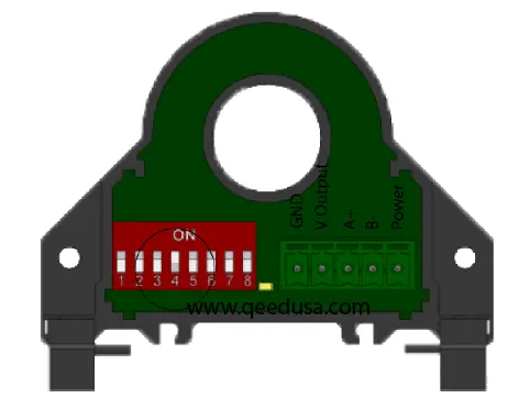
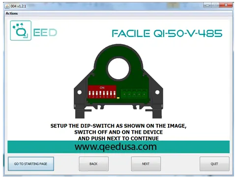
- DIP Switch Programmable
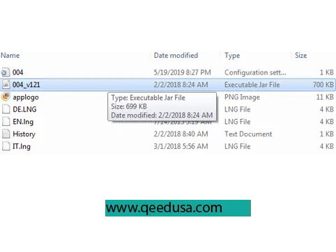
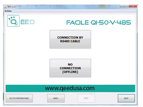
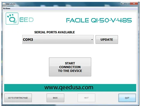
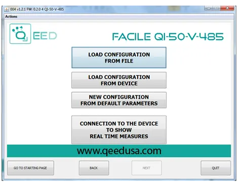
- PC Programmable
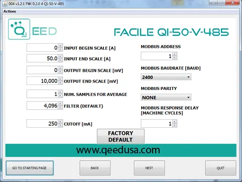
- 0-25 / 0-50 Amp Input
- 0-10 V Output
- DIN Rail Mount
What does the QI-50-V-485 do?
Converts AC Current into Modbus.Converts DC Current into Modbus.
Converts AC Current into 0-10Vdc.
Converts DC Current into 0-10Vdc.
Modbus Current Transducer
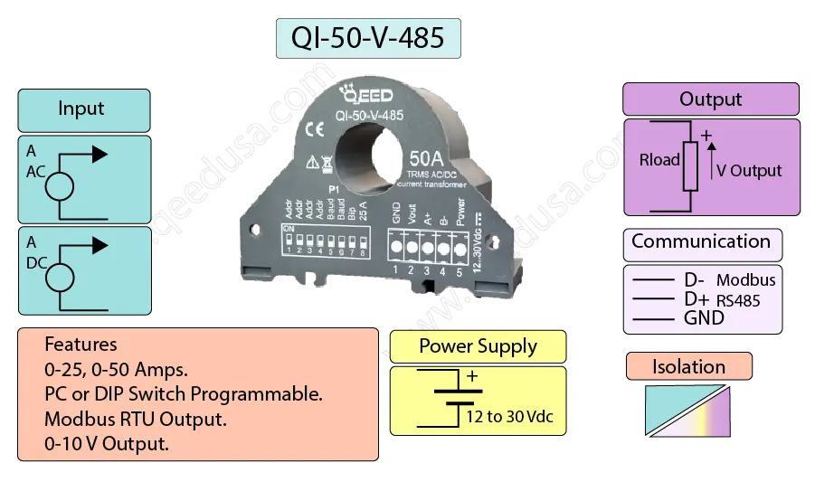
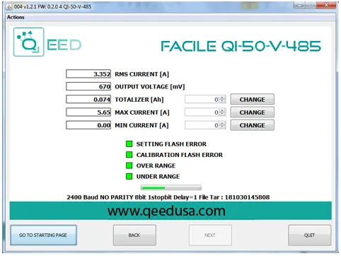
The QI-50-V-485 is a versatile Modbus current transducer with Modbus and 0-10V DC outputs. It measures the True RMS value of AC or DC current with 12-bit resolution and 0.5% accuracy.
The device supports 0-25A or 0-50A full-scale ranges, selectable via DIP switch, and is also PC programmable for added flexibility.
It features 3000 Vac isolation to eliminate ground loops, making it ideal for industrial environments.
Easily mounted on a DIN rail, its baud rate and address are configurable via DIP switches and PC programming.